Three-Dimensional Finite Element Analysis
of a Total Knee Prosthesis
RAJ
BASU and BONEY MATHEW
Mathson Industries Inc.
1845 Thunderbird Street
Troy, MI 48084
A common problem
with knee prostheses is wear failure of the polyethylene
tibial plateau. The objective of this study was to
compute the stresses generated in the polyethylene and
to determine how the stresses varied with changes in the
minimum polyethylene thickness and the joint load. High
stresses generated in the polyethylene thickness and the
joint load. High stresses generated in the polyethylene
lead to failure by wear.
A
three-dimensional finite element model of a metal-backed
polyethylene tibial component with a conforming femoral
component was generated. Nonlinear GAP elements were
used to define the contact between the articulating
femoral and tibial surfaces. Four load cases were
considered. Two cases simulated level walking and two
simulated stair climbing. For each activity, one load
case considered the joint load as being equally shared
between the two condyles, while the other case assumed
that the joint load was acting only on one condyle. Six
different model cases were considered each having a
different minimum polyethylene thickness (tmin). Each
model case was analyzed for each of the four load cases.
The maximum Von
Mises stress exceeded the yield strength of polyethylene
for all thicknesses for the extreme load case of stair
climbing. For tmin = 8 mm, the maximum Von Mises stress
was less than the yield strength for al the other load
cases. The maximum shear stress was less than the
failure value for all cases. The optimum minimum
polyethylene thickness for the tibial component of a
knee prosthesis was concluded as 8 mm. With this
thickness, the polyethylene would not yield during
normal level walking and during stair climbing, yielding
and subsequent wear of the polyethylene would be
reduced. For a minimum thickness greater than 8 mm, the
undesirable effect associated with over-resection of
bone become dominant.
INTRODUCTION
The knee is the
largest synovial joint of the human body. The movement
at the knee joint involves mainly flexion-extension, as
well as medial-lateral rotation and abduction-adduction
in the frontal plane. There is also limited gliding of
the femoral condyles on top of the tibial plateau.
There are
instances when the knee joint becomes degenerated due to
disease or damaged due to injury. Joint degeneration due
to osteoarthritis and rheumatoid arthritis is a common
problem in the elderly. Total knee replacement is often
a successful treatment.
The primary
indications for total knee arthroplasty are pain,
stiffness, instability and deformity at the joint.
However, whether the patient requires a knee replacement
or not also depends on other factors such as age and
life-style, the precise nature of the under-lying
disease and the clinical state of the affected knee.
A total knee
prosthesis includes a tibial component and a femoral
component. The femoral component consists of a
bicondylar surface, made of a biocompatible metallic
material, such as Co-Cr alloy, that articulates on top
of the tibial plateau. The tibial component consists of
an ultra-high molecular weight polyethylene (UHMWPE)
bicondylar plateau fixed on top of a metallic tray with
a central stem or short pegs on the underside.
It has been
found that a prosthesis will primarily fail due to the
failure of the tibial component. More often than not, a
tibial component will fail due to polyethylene wear of
the tibial plateau.
Wright, et al
(1), in 1982, studied the mechanism of wear, from the
analysis of retrieved implants. Whenever materials are
in moving contract and transmitting large loads,
material damage occurs. The resulting damage may occur
in different modes that are collectively termed wear.
BACKGROUND
Kilgus, et al
(2), in 1991, reported 8 revisions (4.5% of the series)
in a series of 176 PCA knees, all due to tibial
polyethylene wear, at an average of 60 months. Nine
additional knees (5.1%) had thinning of greater than 30%
of the initial polyethylene thickness. Jones, et al (3),
in 1992, in their 5 year follow-up study reported that
extensive wear on the medial side of the polyethylene
surface led to failure in 5 (4.6%) of a series of 108
uncemented PCA knees. Engh, et al (4) in 1992, observed
severe wear of the polyethylene tibial plateau in 51% of
the 86 metal-backed tibial components retrieved after an
average of 39.5 months in situ.
Tsao, et al (5),
in 1993, reported a 6.6% failure rate due to severe
polyethylene wear in a series of 487 PCA knees, all due
to polyethylene wear, after a period of 4.5 years.
Kilgus, et al (2), in 1991, discussed the factors that
play an important role in the wear failure of the
polyethylene. The factors are manufacturing processes,
polyethylene thickness, material property of the
polyethylene, tibio-femoral articular geometry, knee
alignment, femoral component surface bearing material
and modularity of the tibial inserts and trays.
Bartel, et al
(6,7) in 1985 and 1986, used an elasticity solution to
express the contact stresses as a function of the tibial
plateau thickness and recommended a minimum polyethylene
thickness of 8 mm. Finite element analysis (FEA) was
used to compare the maximum contact stress and to
determine the maximum principal and maximum shear
stresses. Collier, et al (8) in 1991, used a finite
element method to study the maximum contact and Von
Mises stresses on the polyethylene plateau as a function
of the polyethylene thickness and recommended a minimum
polyethylene thickness of 6 mm. The criterion for
failure was that yielding occurred when the Von Mises
stress exceeded the uniaxial yield strength.
Whiteside, et al
(9), in 1985, observed that resection of excessive bone
from the distal femur raises the join line and alters
the kniematics of knee flexion. Volz, et al (10), in
1986, observed that resection of excessive bone from the
proximal tibia will leave bone with decreased strength
to resist compression, thus risking that the
polyethylene thickness of the widely used tibial
components do not use the recommended thickness of 6 - 8
mm.
OBJECTIVE
The objective of
this study was to investigate the stresses in the
polyethylene tibial plateau that leads to wear. A three
dimensional finite element model of a metal-backed
polyethylene tibial component with a conforming femoral
component was developed. The parameters that were varied
were the polyethylene thickness and the applied loading
conditions. The failure criteria was as per the Maximum
Shear Stress Theory and the Maximum Distortion Energy
Theory of failure.
The hypothesis
of the study was that the maximum Von Mises stress, the
maximum contact stress, the maximum principal stress and
the maximum shear stress, in the polyethylene tibial
plateau decreases with an increase in the minimum
polyethylene thickness and the increases with an
increase in the applied joint load.
MATERIALS AND
METHODS
The model
geometry was based on a commercial Kinemax® Total Knee
manufactured by Howmedica, Inc. The 3-D finite element
model was generated using the FE package. COSMOS/M.
Because of the symmetry, only half of the components
were modeled to save computer time and memory space (Fig
1).
The femoral
component, the tibial plateau and the metal tray were
modeled using 8 noded, 3-D SOLID elements. Similar
element type was used to model the soft rubber-like
cushioning elements. The list of material properties is
show in Table 1. All the materials were assumed to be
homogeneous, isotropic and linearly elastic.
The contact
between the femoral and tibial components was modeled
using one-noded GAP elements. The advantages of using
one-noded GAP elements are that the exact location of
the point of contact and the direction of the contact
forces need not be known a prior and the nodal points on
the contacting surfaces need not match each other.
Previous
investigations by other authors have used a total
resultant load of three times the body weight (3BS) at
the knee joint to consider leverl walking. MOrrison
(12), in 1970, estimated the compressive force at the
knee as 4.8 BW for stair climbing. Two cases simulated
level walking and two simulated stair climging. The
joint loads considered were 3 BS and 5 BW respectively.
For each activiy, one load case considered the joint
load as being equally shared between the two condyles, 2
C; while the other case assumed that the joint load was
acting only on one condyle, 1 C. The magnitudes of the
joint load for the four cases were 1250 N (3 BW, 2 C),
2084 N (5 BW, 2 C), 2500 N (3 BW 1C) and 4167 N (5 BW, 1
C). Six different model cases were considered, each
having a different minimum polyethylene thickness tmin).
The values for tmin were 2, 3, 6, 8, 10 and 11 mm.
Each model case
was analyzed for each of the four load cases. The
analysis method used was nonlinear static analysis. A
force control technique was used in the analysis where
the loads were applied in incremental steps. The Newton-Raphson
(NR) iterative scheme was adopted which had a high
convergence rate.
RESULTS AND
DISCUSSION
The Von Mises
stress plots for the model case, tmin = 2 mm are shown
in Figs. 2 and 3. The variation of the maximum Von Mises
stresses with tmin is shown in Fig. 4. It was observed
that when tmin was below 4 mm, the stresses increased
rapidly with decreasing
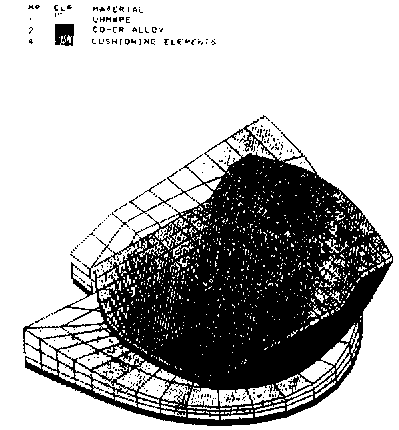
FIG 1 MATERIAL
PROPERTIES
Table 1. material
Properties.
|
Material |
Young's
Modulus (MPa) |
Poisson's Ratio |
| UHMWPE |
900.00 |
0.30 |
| Co-Cr
Alloy |
210000.00 |
0.30 |
| Cushioning
Elements |
7.75 |
0.49 |
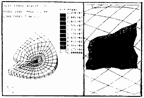
FIG 2 VON MISES STRESS
PLOT
(Model Case:
tmin = 2 mm, Load Case: 3 BW, 1, C)
.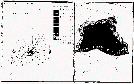
FIG 3 VON MISES STRESS
PLOT
(Model Case: tmin = 2 mm, Load Case: 5 BW, 1, C)
thickness. A
transition occurred for thicknesses between 4 - 8 mm,
with the stresses decreasing slowly as tmin increased
from 6 mm to 8 mm. For tmin = 8 mm and greater, the drop
in stresses was minimal. The other stress curves
(maximum normal, maximum principal and maximum shear
stress curves) were observed to have similar patterns.
Table 2 shows the maximum stresses for the model case,
tmin = 8 mm. The Von Mises stress plots for the model
case, tmin = 8 mm are shown in Figs 5 and 6. The maximum
Von Mises, contact and principal stresses were at the
top central node. The maximum shear stress was observed
1 mm to the left of the top central node.
CONCLUSIONS
The nature of
the variation in the stresses with the change in the
minimum polyethylene thickness and the joint load was
similar to those in previous studies (6,8).
The results
validated the hypothesis. When tmin was below 4 mm, the
stresses increased rapidly with decreasing thickness. A
transition occurred from 4 - 8 mm. For tmin = 8 mm and
greater, the drop in stresses was minimal. The maximum
Von Mises stress always exceeded yield strength of
polyethylene for the extreme load case. For the tmin = 8
mm, max. Von Mises stress was less than yield strength
for all other load cases. Optimum minimum thickness of
polyethylene should be 8 mm. Good compromise with
undesirable problems of over-resection of bone.
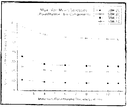
FIG 4. Maximum Von
Mises
Stress vs. Minimum Polyethylene Thickness
Table 2. Maximum
Stresses Generated for Different Load Cases for the
Model Case, tmin = 8 mm.
| Load
Case |
Load
(N) |
Maximum
Contact Stress (MPa) |
Maximum
Principal Stress (MPa) |
Maximum
Von Mises stress (MPa) |
Maximum
Shear Stress (MPa) |
| 3 BW, 2 C |
1250 |
11,461 |
11,487 |
8,944 |
1,095 |
| RBW, 2 C |
2084 |
19,135 |
19,178 |
14,942 |
1,826 |
| 3BW, 1 C |
2500 |
22,984 |
23,035 |
17,952 |
2,190 |
| 5 BW, 1 C |
4167 |
40,852 |
41,018 |
32,240 |
3,834 |
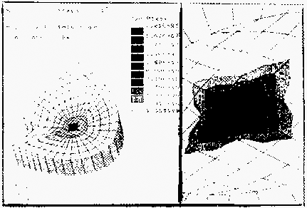
Fig. 5. Von
Mises Stress Plot
(Model Case: tmin = 8 mm, Load
Case: 3 BW, 1 C).
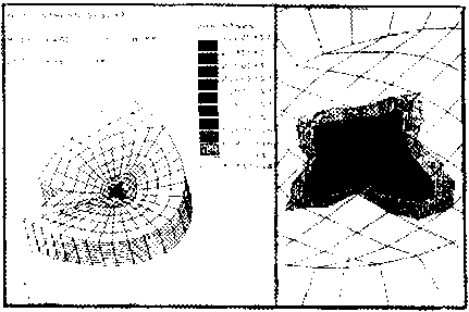
Fig 6. Von Mises
Stress Plot
(Model Case: tmin = 8 mm, Load
Case: 5 BS 1 C).
ACKNOWLEDGMENTS
The authors
would like to thank Dr. Mary C. Verstraete, Dr. Michael
J. Askew, Dr. Glen O. Njus and Ms. Marnie M. Saunders at
The University of Akron, Arkon, OH; Mr. Nicholas A.
Plaxton at Mt. Sinai Medical Center, Cleveland, OH; and
Ms. Maria Lotoczky and Ms. Natayla Zorina at Mathson
Industries, Inc., Troy, MI for their valuable
suggestions and assistance on this project.
REFERENCES
1. T. M.
Wright, R.W. Hood and A. H.l Burstein, “Analysis of
Material Failures,” Orthop, Clin. North Am., Vol. 13,
1982, pp 33 - 44.
2. D. J.
Kilgus, J. R. Moreland, G.A. Finerman, T. T. Funahashi
and J. S. Tipton, “Catastrophic Wear of Tibial
Polyethylene Inserts,” Clinical Orthopaedics and Related
Research, Vol. 273, 1991, pp. 223 - 231.
3. S. M.
Jones, I. M. Pinder, C. G. Moran and A. J. Malcolm,
“Polyethylene Wear in Uncemented Knee Replacements,”
Journal of Bone and Joint Surgery - British Volume, Vol.
74, 1992, pp. 18 - 22.
4. C. A.
Engh, K. A. Dwyer and C. K. Hanes, “Polyethylene Wear of
Metal-backed Tibial Components in Total and
Unicompartmental Knee Prosthesis,” Journal of Bone and
Joint Surgery - British Volume, Vol. 74-B, 1992, pp. 9 -
17.
5. A.
Tsao, L. Mintz, C. R. McRae, S. D. Stulberg and T.
Wright, “Failure of the Porous-Coated Anatomic
Prosthesis in Total Knee Arthroplasty due to Severe
Polyethylene Wear,” Journal of Bone and Joint Surgery,
Vol. 75, 1993, pp. 19 - 26.
6. D. L.
Bartel, A. H. Burstein, M. D. Toda and D. L. Edwards,
“The Effect of Conformity and Plastic Thickness on
Contact Stresses in Metal-Backed Plastic Implants.”
Journal of Biomechanical Engineering, Vol. 107, 1985,
pp. 193 - 199.
7. D. L.
Bartel, V. L. Bickness, M. S> Ithaca and T. M. Wright,
“The Effect of Conformity, Thickness and Material on
Stresses in Ultra-High Molecular Weight Components for
Total Joint Replacement,” Journal of BOne and Joint
Surgery, Vol. 68A, 1986, p. 1041.
8. J. P.
Collier, M. B. Mayor, J. L. McNamara. V. A. Suprenant
and R. E. Jensen. “Analysis of The Failure of 122
Polyethylene Inserts From Uncemented Tibial Knee
Components,” Clinical Orthopaedics and Related Research,
Vol. 273, 1991, pp. 232 - 242.
9. L. A.
Whiteside and R. Summers. “The Effect of the LEvel of
Distal Femoral Resection on Ligament Balance in Total
Knee Replacement.” The Knee: Papers of the First
scientific Meeting of the Knee Society, Baltimore,
University Park Press, 1985, pp. 59 - 73.
10. R. G.
Volz, S. G. Kantor, C. Howe and M. McMurtry, “Factors
Affecting Tibial Component Stability: A comparative
Study,” Total Arthroplasty of the Knee: Proceedings of
the Knee Society, 1985 - 1986, Rockville, Maryland,
Aspen Publishers, 1987, pp. 109 - 120.
11. K. J.
Chillag and E. Barth, “An Analysis of Polyethylene
Thickness in Modular Total Knee Components,” Clinical
Orthopaedics and Related Research, Vol. 273, 1991, pp.
261 - 263.
12. J. B.
Morrison, “The Mechanics of the Knee Joint in Relation
to Normal Walking,” Journal of biomechanics, Vol. 3,
1970, pp. 51 - 61.
|